apt-get
install libftdi0
and apt-get install libftdi-dev
for developing purposes)
|
|
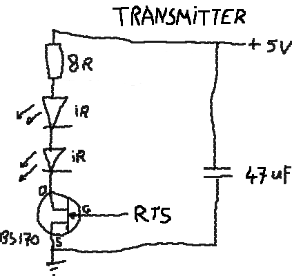 |
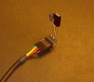
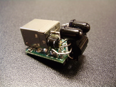 Albert's 2nd prototype: very small with MM232R |
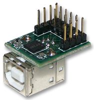 the MM232R module |
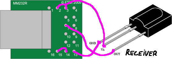 receiver example with MM232R | ||
apt-get install libftdi0 libftdi-dev libtool help2man
man2html)mkdir ~/lircftdicd ~/lircftdicvs -d:pserver:anonymous@lirc.cvs.sourceforge.net:/cvsroot/lirc login
cvs -z8 -d:pserver:anonymous@lirc.cvs.sourceforge.net:/cvsroot/lirc co lirc
cd lirc
cvs update
setup.sh
&& make
(note: don't
use make install to avoid
overwriting your existing LIRC daemon)"Driver configuration" -> "USB devices"
-> "FTDI FT232-based IR Receiver""Save configuration & configure"/etc/lircd.conf ready (see
LIRC website for this)sudo daemon/lircd -n (the -n
avoids daemon mode)sudo irw'
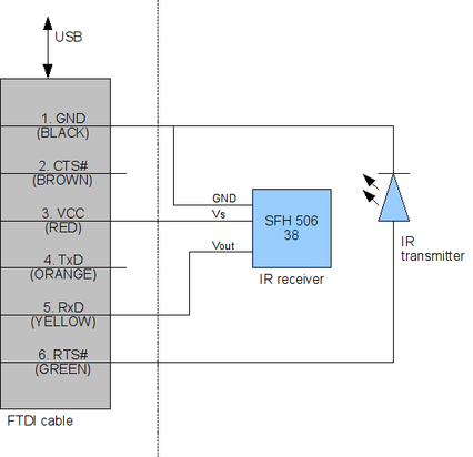
in another shell| vendor | vendor code (default 0x0403 for FTDI) |
| product | product code (default 0x6001 for FT232) |
| desc | description string (default = not defined) |
| serial | serial string (default = not defined) |
| input | input bit number (0..7, default = 1) 0 = TxD 1 = RxD (default) 2 = RTS 3 = CTS 4 = DTR 5 = DSR 6 = DCD 7 = RI |
| output |
see input |
gcc rc5.c -lftdi -o rc5'./rc5 12 (switch TV to stdby)./rc5 0 (switch to channel '0' on TV) ./rc5 32 (zap P+ on TV)Quick way to lookup serial number:
plug into usb port (only 1 though)
udevadm info -q all -n /dev/ttyUSB0